When it comes to commercial fleet vehicles, Dana knows there’s no time for downtime. For fleet managers and service techs, every second counts when a vehicle is down with a broken driveshaft. With over twelve thousand part numbers within the Spicer® product portfolio, we recognized the need to find a better way for our customers to locate replacement parts.
The Spicer ReadyShaft Dana EZ-ID Tool is our easy-to-use, streamlined solution for identifying the Genuine Spicer® driveline parts needed to get your fleet vehicles fixed and back on the road, fast.
Complete Driveshafts Built and Shipped Within 24 Hours
The Spicer ReadyShaft Program for commercial vehicles is a quick-ship program created to reduce the downtime of your vehicle. Through the program, Dana builds and ships warrantied driveshaft assemblies within 24 hours, with free next-day delivery. And with quick part identification through the Spicer ReadyShaft Dana EZ-ID Tool, you can get complete driveshaft assemblies delivered to your door in less than 48 hours.
Quickly Identify Spicer Driveline Replacement Parts
The Spicer ReadyShaft Dana EZ-ID Tool simplifies part identification without product numbers with an easy-to-follow 10-step process for collecting the dimensional data of the part. This information can then be utilized to identify the correct replacement driveline assembly parts needed.
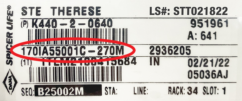
To begin using the platform, visit DanaAftermarket.com and click on the Spicer ReadyShaft logo on the home page. If you have the part number, great! Simply type it into the entry field (Fig. 1) to generate your ReadyShaft part number (Fig. 2).
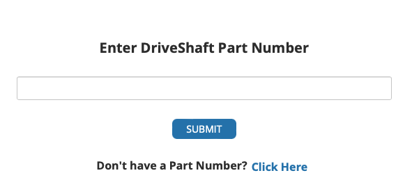
But what if you don’t have a part number? No problem! Click on Click Here (Fig. 1). Once you have read the disclaimers and clicked Continue, move on to complete the following steps.
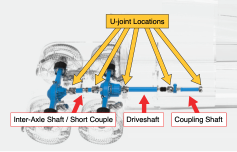
Step 1. Select the Spicer ReadyShaft Type
Start by identifying where on the truck the shaft came from by selecting the appropriate button from the following options:
1. Inter-Axle Shaft or Short Couple
2. Driveshaft
3. Coupling Shaft
Step 2. Select Short Couple or Inter-Axle Shaft
Determine between a short couple or inter-axle shaft. Some helpful key identifying information is that short couple doesn’t include tubing; if tubing is present, this indicates an inter-axle shaft. Inter-axle shafts also contain two welds.
Step 3. Identify Yoke
Determine the type and series of yoke you need with the Spicer® Ruler (Fig. 3) available on DanaAftermarket.com (part number RULER-SPICER-32020).
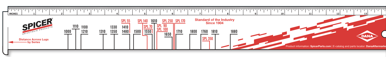
Please note that if you are servicing a half-round yoke, you must replace bolts and straps every time.
Step 4. Select U-Joint Style
Select the U-joint style from the following options:
- 10 Series
- Full Round (4 bearing plates)
- Half Round (2 bearing plates; 2 bearing cups without plates)
- SPL® Series
- Greaseable (4 bearing cups with dual grease zerk in center)
- Service-free (4 bearing cups without grease zerk)
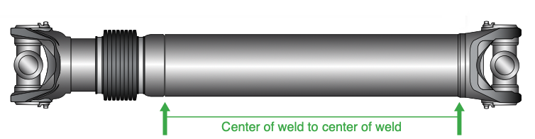
Step 5. Determine Tubing Length
To determine the tubing length, measure from center of weld to center of weld (Fig. 4).
Step 6. Measure Collapsed Length
Compress both ends to collapse the shaft; physical feedback and an audible click will signal that the shaft is collapsed. Once accomplished, measure:
- From center of U-joint to center of U-joint
- Flange face to flange face
- Center of yoke to center of flange face
Step 7. Measure Installed Length
To determine the length of a damaged or missing driveshaft, you can obtain the following dimensions (Fig. 5) to identify the correct part:
- From center of U-joint to center of U-joint
- Flange face to flange face
- Center of yoke to center of flange face
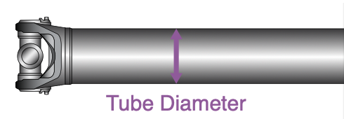
Step 8. Calculate Tube Diameter
Measure your tubing diameter (Fig. 6) in either inches or millimeters.
Please note that if your measurement or selection is not displayed, your driveshaft may not be offered through this program. Please contact your local original-equipment manufacturer to verify your part number.
Step 9. Select Phasing
Phasing refers to how the ears of the yoke are oriented to each other (Fig. 7). Phasing is calculated and implemented at the OE level to counteract vibrations in the driveline.
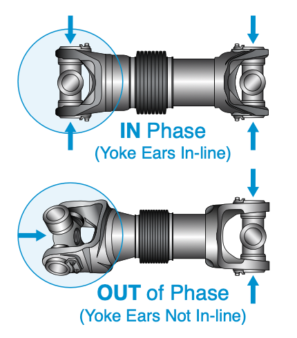
Please note that we do not recommend taking a driveshaft apart and rewelding it so that it’s in phase or out of phase from the original factory specifications.
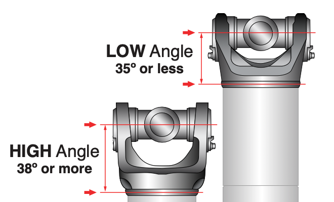
Step 10. Determine Yoke Angle
Calculate high/low yoke angle by measuring from point of weld to center of U-joint at tube/weld yoke (Fig. 8).
Once you select the correct yoke angle, your part ReadyShaft part number will be generated so you can place your order.
Genuine OE-Quality Parts. Award-Winning Part Identification.
Winner of the 2023 MEMA Aftermarket Suppliers Excellence Award, the Spicer ReadyShaft Dana EZ-ID Tool is helping customers across the globe optimize the uptime of their fleet by taking the hassle out of finding parts without product numbers. Test it out for yourself at https://spicerparts.com/campaign/ez-id.